French
German
Dutch
Unavailable
Unavailable
![]()
![]()
Please read this entire page before making
a decision to try this fix for ('Yourself' or 'Emailing Me').
As with all the other projects on my
website.
Please note that I, nor the Translators, will not be held responsible in anyway, shape or
form, if you damage your equipment whilst trying this fix yourself.
|
French |
German |
Dutch |
Unavailable |
Unavailable |
|
|
|
As ever, if you want anything doing, do
it yourself. Surgery time .......
With a little help from 'wakko' on Pocket
GPS
World: Forums
After this modification you will have a
fully re-chargeable, working unit.
You won't be able to Active sync via cable.
Perhaps buy a USB IR dongle and sync via infrared. IR is built into my
laptop :-)
I also have a USB SD card reader for large file transfer.
Undo the four screws on the back of the
unit. Not the one on the Gps bit.
With the screen facing you, use a butter knife to 'pop' the bottom right
corner of the casing apart.
Do the same for the bottom left side.
Lay it screen face down, and 'pop' the rest of the case apart.
There is a small wire between the back casing and the front (circuit
board).
Either disconnect the wire, (little gold plug on the circuit board),
or lay the back casing to one side.
The
unit in these two photo's is not broken. (Yet. Ha ha ha,
famous last words ! )
I recommend you carefully remove the silver socket if yours is broken.
A close-up
I did a some continuity checks with my multimeter and found out these 2 solder pads are directly connected to the charger socket. The POS one has the full 5V on it from the charger and the GND has a direct connection to it. So these pads are obviously before any on-board circuitry.
NORMALLY, when the charger is plugged
in, none of the batteries 5 wires (or the 6 terminals) has 5V on it.
One has 4.?V on it.
So a wrong connection directly to battery leads could cause Explosion !!
Should the charger socket break or collapse, solder 2 wires to these pads with a suitable connector etc on the other end.
Now there's a very clever trick to take the stress off the wires soldered to the motherboard.
I'm to nice to you peeps.
Dave emailed me wanting to know which
wires to put a plug on with an in-car charger.
Black is GND, connect the Red and White together +5V
23 Jan 2007 - I can confirm that this works. Just done the mod to my bosses MIO 168
25th Oct 2007 - On this Medion I used a
part of the original charger plug. I had to remove a small piece of the
casing.
A much more robust approach.
If you use a socket from some other source eg, Nokia phone,

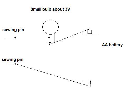
Please build yourself a simple continuity tester before emailing me.
If you can't work out what wires to wire where, give up !!!
If you found this page usefull, I can receive donations via PayPal ;-)
If you want me to fix your unit I will,
for about £30, email me. I don't offer a guarantee.
Each case is different. I don't know if you've already knackered your
device before sending it to me.